Saturday, November 26, 2022

How to Measure Ampere using ACS712 current Sensor with Arduino

 How to Measure Ampere using  ACS712 current Sensor with Arduino

Have you ever stopped and wonder the amount of current each of your electrical appliances require? Well, it’s a tedious process to know it all but that’s where the functionality of a current sensor comes to play. With different devices having different current requirements, if a wrong amount of current is fed to them, it may result in severe circumstances (overloading, etc.). Hence, it’s necessary for one to monitor the required current for applications, and that’s when people turn to a current sensor to do the job, notably the ACS712 AC/DC Current sensor.

What is the ACS712 AC/DC Current Sensor?


The ACS712 is a fully integrated, hall effect-based linear current sensor with 2.1kVRMS voltage isolation and a integrated low-resistance current conductor. Technical terms aside, it’s simply put forth as a current sensor that uses its conductor to calculate and measure the amount of current applied.


The features of ACS712 include:

  • 80kHz bandwith
  • 66 to 185 mV/A output sensitivity
  • Low-noise analog signal path
  • Device bandwith is set via the new FILTER pin
  • 1.2 mΩ internal conductor resistance
  • Total output error of 1.5% at TA = 25°C
  • Stable output offset voltage.
  • Near zero magnetic hysteresis

For more information on ACS712 pinout, schematics, and circuit diagram, you can download ACS712 datasheet here!

How does the ACS712 Current Sensor work?

Now that we’ve had an idea of what the ACS712 is capable of, we’ll take a look at its working principle. Well, when it comes to how a current sensor works, it can either be done through direct or indirect sensing. For the ACS712, it uses indirect sensing.

  • For current sensors that work by direct sensing, ohm’s law is being applied to measure the drop in voltage when flowing current is detected.

Here’s how the ACS712 work (Simplified):

  • Current flows through the onboard hall sensor circuit in its IC
  • The hall effect sensor detects the incoming current through its magnetic field generation
  • Once detected, the hall effect sensor generates a voltage proportional to its magnetic field that’s then used to measure the amount of current

ACS712 Current Sensor Applications

We’ve established a general idea of what current sensors are applicable for earlier. Well, with the ACS712 IC being able to detect both AC/DC current, it can be used in a wider range of applications apart from electrical appliances. Be it Arduino/other microcontroller usages, or industrial, commercial, and communication applications, it can be found applicable.

Here are the common list of applications:

  • Motor speed control in motor control circuits
  • Electrical load detection and management
  • Switched-mode power supplies (SMPS)
  • Protection for over-current

ACS712 Current Sensor Arduino Guide

The ACS712 current sensor can be connected to your Arduino board through a series of jumper wires connections based on its pinout. However, here at Seeed, we understand the complications and complexity of doing so. Hence, we’ve decided to provide a tutorial for our Grove – ±5A DC/AC Current Sensor (ACS70331) to display how easy our Grove plug-and-play system is!

Here’s what you need for today’s tutorial:


Download Library


Code Below


------------------------------------------------------------------------------------------------------------

#include "ACS712.h"


/*

  This example shows how to measure DC current

*/


// We have 30 amps version sensor connected to A1 pin of arduino

// Replace with your version if necessary

ACS712 sensor(ACS712_30A, A1);


void setup() {

  Serial.begin(9600);


  // This method calibrates zero point of sensor,

  // It is not necessary, but may positively affect the accuracy

  // Ensure that no current flows through the sensor at this moment

  sensor.calibrate();

}


void loop() {

  // Get current from sensor

  float  I = sensor.getCurrentDC();

  Serial.println(String("I = ") + I+ " A");


  // Wait one second before the new cycle

  delay(100);

}

---------------------------------------------------------------------------------------------------------------


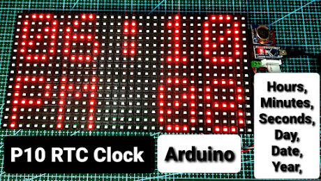
Thursday, November 18, 2021

P10 RTC clock Code Download Page


Your download will begin in 600 seconds.


You have to stay on this page till timer goes off then only you will get the file from google drive.


Arrange all the components as per the diagram connection,

upload the hex file using Arduino builder software, if you have not used this software before kindly watch the video given below,


Your download will contain these two files,  and upload hex file using Arduino builder software.


P10 RTC Clock using Arduino

P10 RTC Clock using Arduino


In This Project I will show you how to make Arduino Based Large RTC clock on P10 Board, 


Items Required, 

1. P10 Board

2. Arduino Nano / Uno

3. RTC 1307 Module

4. P10 Board flap cable

5. 5 volt power supply

6. Push button - 3

7. Zero PCB

8. PCB Male  Header


I hope you are familiar with p10 Board Connectors


I you are following my youtube Channel then you have sound knowledge of Arduino Nano and its programming


Arrange the Components on Zero PCB and Programme Arduino Nano with the Hex File available in the download button below.


Hex File Download


Friday, November 12, 2021

Arduino based digital Thermometer Temperature Gun by Manmohan Pal

 Arduino based digital Thermometer Temperature Gun by Manmohan Pal


Download Code:


In this video i will show you how to make a temperature gun using MLX90614 and OLED screen, project is simple, small and usefull, it can measure surrounding temperature as well as object temperature, as we know MLx90614 is a contactless temperature sensor thus it can measure from 10 CM distance. if you are new to MLX90614 sensor kindly watch my previous introduction video on it MLX90614 Contactless Temperature Sensor with Arduino https://youtu.be/Ky99dJFzsRQ OLED display, How to connect OLED screen With Arduino https://youtu.be/XEbRnBR4yKk if you are new to Arduino Nano kindly watch these videos 1) " Arduino Nano Unboxing| Uploading First Program on Arduino Nano- By Manmohan Pal" https://www.youtube.com/watch?v=OxQcPwc8Wl0 2)" Arduino Nano Driver (ch340) install and troubleshoot by Manmohan Pal " https://www.youtube.com/watch?v=D94t3Bm9plA 3) "Arduino Nano Code Uploading Error fixed/Bootload Arduino Nano/ ICSP Connaction/ Bootload any Atmega" https://www.youtube.com/watch?v=8RE8URgENUg Manmohan Pal Email: mannmohanpal@gmail.com Whatsapp: 8989811397 Facebook: https://www.facebook.com/mannmohan.pal.7 Facebook Page: https://www.facebook.com/Electronics-by-Manmohan-Pal-1802344069857656/ Instagam: #manmohan.pal Twitter: @ManmohanPal15 Youtube channel: https://www.youtube.com/user/mannmohanpal Blog: http://electronics4ubymanmohanpal.blogspot.in/

My other Youtube Channel


Manmohan Pal

https://www.youtube.com/channel/UCDnhARnHOEIPuNIEp5vPdGQ


Easy Electronics By Manmohan Pal

https://www.youtube.com/channel/UC3o5qRRPPJUhhiHKrJX-yhg

NodeMcu Esp8266 by Manmohan Pal

https://www.youtube.com/channel/UC4FXFd3RxL-Q1ZERJ4JvqJA Other videos you may find use ful Playlist for Arduino Tutorial https://www.youtube.com/watch?v=JMjJDCpNVc0&list=PL-W6psKgiPqX57846z5htDft0YuR8bXSY How to make bare bone Arduino on breadboard (ATMEGA328P) by Manmohan Pal https://www.youtube.com/watch?v=oA_NNvG4dEU Bluetooth Car using Arduino + HC05 +Android APP by Manmohan Pal https://www.youtube.com/watch?v=1T0QCpnQrOo&t=186s RF Remote Control Robo Car using 433Mhz RF Module by Manmohan Pal https://www.youtube.com/watch?v=safPeO38_2A How To Identify 8*8 Led Matrix Pins by Manmohan Pal https://www.youtube.com/watch?v=ZXF62U0ziJ8 RF Remote Control Car Using 433 Mhz RF transmitter and Receiver Kit by Manmohan Pal https://www.youtube.com/watch?v=rcaQluS7Gzw RF Remote Control Car Using 433 Mhz RF transmitter and Receiver Kit by Manmohan Pal https://www.youtube.com/watch?v=rcaQluS7Gzw RF Remote Control Circuit Using 433 Mhz Module and HT12E Encoder and HT12D Decoder IC by Manmohan https://www.youtube.com/watch?v=51TNQiaXm3U IC L293 Moter Driver H Bridge IC by Manmohan Pal https://www.youtube.com/watch?v=1Gh-aVm5rDg RF Remote Control Circuit Using 433 Mhz Module and HT12E Encoder and HT12D Decoder IC by Manmohan https://www.youtube.com/watch?v=51TNQiaXm3U Wireless 4 Channel 433 Mhz RF Remote Control Transmitter and Receiver Unboxing by Manmohan Pal https://www.youtube.com/watch?v=ZFjDGuFBMnI 433 Mhz RF Module Tx and Rx with Arduino Nano, RF Remote Control Circuit by Manmohan Pal https://www.youtube.com/watch?v=JHN7kgguCG8 Wireless 4 Channel 433 Mhz RF Remote Control Transmitter and Receiver Unboxing by Manmohan Pal https://www.youtube.com/watch?v=ZFjDGuFBMnI RF 4 Channel Remote Control Relay Module using 433 Mhz RF Transmitter and Reciever bu Manmohan Pal https://www.youtube.com/watch?v=1bgBXruwxfE&t=58s https://www.youtube.com/watch?v=C1qGVaGgGOo 433 Mhz RF Module Tx and Rx with Arduino Nano, RF Remote Control Circuit by Manmohan Pal https://www.youtube.com/watch?v=JHN7kgguCG8&t=607s Remote Control Relay Module 4 Channel 5 volt by Manmohan Pal https://www.youtube.com/watch?v=67_CzDsuyfw Arduino Nano Unboxing| Uploading First Program on Arduino Nano- By Manmohan Pal https://www.youtube.com/watch?v=OxQcPwc8Wl0

Arduino Based Temperature Gun code Download Page


Your download will begin in 600 seconds.


Wednesday, October 27, 2021

Saturday, January 2, 2021

Control Multiple Seven segment Displays using Shift Register 74HC595 by Manmohan Pal


 In this video I will show you how to control seven segment digits using 3 pins on Arduino, Using Shift Register 74595 we can do so easily, Beauty of using this IC is ,we can use Multiple Display using the same 3 Pins of Arduino, hope you will enjoy learning about this IC.


Video Part 1:https://www.youtube.com/watch?v=QI1IJLB42G8 Video Part 2: https://www.youtube.com/watch?v=GXgH4jcbi0o&t=1038s


Circuit Diagram: https://arduinobymanmohan.blogspot.com/2021/01/control-multiple-seven-segment-displays.html Code Link: https://arduinobymanmohan.blogspot.com/2021/01/control-multiple-seven-segment-displays.html


Recently these PCB's are Designed by me to control 6 Seven segment Digits using NodeMcu ESP8266,
These PCB's have capabilities to control 3.5 volt to 12 volt or Higher volt Seven Segment digits, Small Midium and Large size Seven segment can be attached on this pcb, and as the NodeMcu have Wifi capibilities, thus we can make internet clock using this PCB,

BUY This PCB @ Rs. 499/-
Order Us On WhatsApp +91 8989811397

Advantages of This PCB

1) Supports 12 vot / 9 volt / 5 volt input
2) 12 volt / 9 volt / 3 volt Seven Segment Displays can be controlled
3) 0.5 inch/ 1 inch/ 1.5 inch Seven segment displays can be mounted on same PCB
4) supports Common Anode as well as Common Cathode seven segment displays
5) we can extend /add next PCB for operating next 6 digits
6) have facility to Add LDR to control brightness of Seven Segment Digits with Ambient Light
7) As it have IR Receiver slot thus we can give multiple input using different Remotes
8) As it have Shift Register 74595 it have practically unlimited output pins
9) same PCB can be used for Home automation as it have Wifi, IR remote and Unlimited OUTPUT Pins
10) Can be used to make Automatic Staircase lights by connecting 2 IR proximity Sensors upto 42 stairs
12) Can be used to make large Score board for stadium or Studios
13) PCB have facility to add Temp. Sensor thus can display same of Seven Segments
14) have 6 digits thus we can make small or huge stop Watch using this PCB.
15) I will make Huge RGB seven Segment Digits and control them using same PCB

Finally this PCB supports
NodeMCU +Shift Registers 74595 + IR Reciever TSop1738
Thus
Power of Internet/ Wifi / IOT (ESP8266)
Practically Unlimited Output Pins (IC 74HC595)
Practically Unlimited IR Remote  inputs (TSOP 1738)


Video


Six Digit Internet Clock DIY kit


BUY Complete DIY kit NOW @ Rs. 2100/-
Complete DIY kit for 6 digit Internet clock are available with me, if you want to buy, You can order me on WhatsApp on +91 8989811397, This kit also contains outer casing for the circuit.
Order Us On WhatsApp +91 8989811397

List of Components in kit.
1. Node MCU82666 (Preloaded)
2. Seven Segment Displays x 6
3. IC 74HC595 x 6
4. Resistors 100 Ohm x 42
5. Resistors 220 Ohm x 2
6. LED 5 mm x 4
7. Push Button x 3
8. On Off Switch x1
9. Li ion Battery 3.7 Volt x1
10. TP4056 Charging Module x1
11. Micro USB Power Socket x1
12. Buzzer x1
13. NPN Transistor BC547x1
14. IR Receiver TSOP 1738 x1
15. IR Remote Handset x1
16. Fabricated PCB x1
17. Female Pin Header x1
18. Outer Body Casing (Housing)


Functions supported

1) 6 digit time Display
2) 24hr / 12 Hr Mode
3) Set Alarm Functions
4) DATE display
5) IR Remote Control
6) Brightness Adjust (Vol + & Vol-)
7) Hourly beep function
8) Mute function
9) Time Update (Signal Button )
10) Power ON off using Remote
11) Internet Clock (No need to SET time)


As we are using Shift Register IC's we can add next 6 digit to the project, With the little changes in programming we can make much information display on the board,


Code Download


Other Videos of this Play list Control Multiple 7 Segments with Arduino and Shift Register 74HC595 https://www.youtube.com/watch?v=GXgH4jcbi0o&t=1038s Large Seven Segment LED Wall Clock https://youtu.be/GXgH4jcbi0o Add more output pins to Arduino using Shift Register IC 74595 https://youtu.be/xR9CGXS_Fsk Six digit Seven segment Internet clock using Nodemcu https://youtu.be/3tFGPuOlNZA

Make 4 Digit RGB seven Segment


Controller


4 Digit Internet Clock Common Anode RGB segments


video lists. How To Make 8X8 Led Matrix DIY by Manmohan Pal https://www.youtube.com/watch?v=AtG29h2SLpA&t=530s How to display Scrolling Text on 8*8 LED Dot Matrix by Manmohan Pal https://www.youtube.com/watch?v=cO_O4s2Swus&t=300s HOW TO MAKE SCROLLING TEXT LED DISPLAY || 64X8 LED MATRIX BY MANMOHAN PAL https://www.youtube.com/watch?v=-nSiwW6jl6U Bluetooth Car using Arduino + HC05 +Android APP by Manmohan Pal https://www.youtube.com/watch?v=1T0QCpnQrOo&t=186s RF Remote Control Robo Car using 433Mhz RF Module by Manmohan Pal https://www.youtube.com/watch?v=safPeO38_2A How To Identify 8*8 Led Matrix Pins by Manmohan Pal https://www.youtube.com/watch?v=ZXF62U0ziJ8 RF Remote Control Car Using 433 Mhz RF transmitter and Receiver Kit by Manmohan Pal https://www.youtube.com/watch?v=rcaQluS7Gzw RF Remote Control Circuit Using 433 Mhz Module and HT12E Encoder and HT12D Decoder IC by Manmohan https://www.youtube.com/watch?v=51TNQiaXm3U IC L293 Moter Driver H Bridge IC by Manmohan Pal https://www.youtube.com/watch?v=1Gh-aVm5rDg RF Remote Control Circuit Using 433 Mhz Module and HT12E Encoder and HT12D Decoder IC by Manmohan https://www.youtube.com/watch?v=51TNQiaXm3U Wireless 4 Channel 433 Mhz RF Remote Control Transmitter and Receiver Unboxing by Manmohan Pal https://www.youtube.com/watch?v=ZFjDGuFBMnI 433 Mhz RF Module Tx and Rx with Arduino Nano, RF Remote Control Circuit by Manmohan Pal https://www.youtube.com/watch?v=JHN7kgguCG8 Wireless 4 Channel 433 Mhz RF Remote Control Transmitter and Receiver Unboxing by Manmohan Pal https://www.youtube.com/watch?v=ZFjDGuFBMnI RF 4 Channel Remote Control Relay Module using 433 Mhz RF Transmitter and Reciever bu Manmohan Pal https://www.youtube.com/watch?v=1bgBXruwxfE&t=58s https://www.youtube.com/watch?v=C1qGVaGgGOo Touch Switch using NAND gate IC 4011 by Manmohan Pal https://www.youtube.com/watch?v=jIEKWVs8d40 Touch Switch || Toggle aswitch || Touch ON Touch Off Switch using IC 4017 https://www.youtube.com/watch?v=9iA0AtnrL7A 433 Mhz RF Module Tx and Rx with Arduino Nano, RF Remote Control Circuit by Manmohan Pal https://www.youtube.com/watch?v=JHN7kgguCG8&t=607s Remote Control Relay Module 4 Channel 5 volt by Manmohan Pal https://www.youtube.com/watch?v=67_CzDsuyfw Remote control for every home appliance https://www.youtube.com/watch?v=mUuSYWyD7Ic Remote operated light- by Manmohan Pal https://www.youtube.com/watch?v=5oP1SCkVJm8 Remote control Fan- IR remote control Circuit using IC 555 Timer by Manmohan Pal https://www.youtube.com/watch?v=GvAZadfdIAE Arduino Nano Unboxing| Uploading First Program on Arduino Nano- By Manmohan Pal https://www.youtube.com/watch?v=OxQcPwc8Wl0


Wifi Home automation Diy kit

 Wifi Home automation Diy kit By Manmohan Pal Wifi Home Automation Kit Hi, This is Manmohan Pal, I am glad to present a DIY kit for Home Aut...