Blynk App Tutorial iot LED
iOT using Blynk App
To control an LED over the internet using the Blynk app,
you'll need to follow these steps:
### Requirements:
1. **Blynk App** (Install it on your smartphone from the App Store or Google Play).
2. **Microcontroller** (e.g., Arduino, ESP8266, ESP32).
3. **LED** (with appropriate resistors).
4. **Wi-Fi Network**.
5. **Blynk Library** for the microcontroller.
### Step-by-Step Guide
#### Step 1: Setting up Blynk App
1. **Download and Install Blynk**:
- Go to the App Store (iOS) or Google Play (Android).
- Install the **Blynk** app.
2. **Create a Blynk Account**:
- Open the app and create an account or log in.
3. **Create a New Project**:
- Tap on **"Create New Project"**.
- Choose a name for your project (e.g., "LED Control").
- Select your hardware model (for example, "ESP8266" or "Arduino").
- Select the connection type (usually **WiFi**).
- Tap **Create**.
4. **Get the Auth Token**:
- After creating the project, Blynk will generate an **Auth Token**. This is a unique identifier used to connect your hardware to the Blynk server.
- Email this token to yourself, or copy it for later use.
5. **Add Widgets**:
- Add a **Button widget** to the app. This button will control the LED.
- Configure the button:
- Set it to output on a virtual pin (e.g., **V1** for virtual pin 1). V2
- Set the mode to **Switch** or **Push** depending on how you want it to work.
#### Step 2: Setup Microcontroller (Arduino / ESP8266 / ESP32)
1. **Install Blynk Library**:
- Open Arduino IDE and install the Blynk library if you haven’t already.
- Go to **Sketch > Include Library > Manage Libraries**.
- In the Library Manager, search for "Blynk" and install the latest version.
2. **Install Board Support (if needed)**:
- For ESP8266 or ESP32, you'll need to install the board definitions.
- Go to **File > Preferences**, and in the "Additional Boards Manager URLs" field, add:
- For ESP8266: `http://arduino.esp8266.com/stable/package_esp8266com_index.json`
- For ESP32: `https://dl.espressif.com/dl/package_esp32_index.json`
- Then go to **Tools > Board > Boards Manager**, search for **ESP8266** or **ESP32**, and install it.
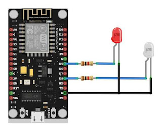
3. **Connect the LED**:
- Connect the positive leg of the LED to a digital output pin (for example, **D5** or **GPIO14* and D8, which is GPIO15*).
- Connect the negative leg of the LED to **GND**.
4. **Arduino Sketch** (Example Code for ESP8266):
Here is the basic code that connects your microcontroller to the Blynk app and controls the LED over the internet.
///////////////////////////////////////////////////////////////////////////////////
#define BLYNK_TEMPLATE_ID "*****************" // paste the copied details from blynk cloud
#define BLYNK_TEMPLATE_NAME "***************"
#define BLYNK_AUTH_TOKEN "******************"

#define BLYNK_PRINT Serial

#include <ESP8266WiFi.h>
#include <BlynkSimpleEsp8266.h>
int led1=14;
int led2=15;

char auth[] = BLYNK_AUTH_TOKEN;
char ssid[] = "******"; //your hotspot name
char pass[] = "******"; //your hotspot password name

void setup()
{
  Serial.begin(9600);
  Blynk.begin(auth, ssid, pass);
  pinMode(led1, OUTPUT);
  pinMode(led2, OUTPUT);

}

void loop() {
  Blynk.run();
}

BLYNK_WRITE(V1){
  int pinValue = param.asInt(); // assigning incoming value from pin V0 to a variable
  digitalWrite(led1,pinValue);
}

BLYNK_WRITE(V2){
  int pinValue = param.asInt(); // assigning incoming value from pin V0 to a variable
  digitalWrite(led2,pinValue);
}
////////////////////////////////////////////////////////////////////////////////////
### Explanation:
- **`Blynk.begin()`**: This function initializes the Blynk connection to the app using the Auth Token, Wi-Fi credentials (SSID and password).
- **`BLYNK_WRITE(V1)`**: This function listens for button presses from the Blynk app on virtual pin V1. When the button is pressed, it turns the LED on (HIGH), and when the button is released, it turns the LED off (LOW).
- **`digitalWrite()`**: This function is used to turn the LED on or off based on the button press.
#### Step 3: Upload the Code to the Microcontroller
- Select the correct board (e.g., **NodeMCU 1.0** or **ESP8266** under **Tools > Board**).
- Choose the correct COM port.
- Upload the code to the microcontroller.
#### Step 4: Test the Setup
1. Once the code is uploaded, open the **Serial Monitor** in the Arduino IDE.
2. You should see a message indicating that the ESP8266 is connected to the Wi-Fi network and the Blynk server.
3. Open the **Blynk App** and press the button widget you added. It should turn the LED on and off based on the button's state.
### Troubleshooting:
- Ensure that your microcontroller has internet access and is connected to the correct Wi-Fi network.
- Double-check your Auth Token.
- Ensure that the correct pin is used for the LED in the code and the hardware setup.
Once everything is set up, you can control the LED from anywhere in the world using the Blynk app!


No comments:
Post a Comment