8x8 LED matrix using Max7219 with Arduino Custom Characters code generator by Manmohan Pal
8x8 LED matrix using Max7219 with Arduino Custom Characters code generator by Manmohan Pal
#LEDMatrix #LEDDotMatrix #8x8LEDmatrix, #max7219, #shiftregister
In this video i will show you unboxing of 8 * 8 LED MATRIX MODULE which is controlled using max7219, the library link is available on my blog, we will see how to generate custom character code and encapsulate it into arduino code,

The MAX7219 is an IC designed to control a 8x8 LED MATRIX. The IC is serial input common-cathode (Common Negative) display drivers that interface microprocessors (or microcontroller) to 7-segment numeric LED displays of up to 8 digits, bar-graph displays, or 64 individual LEDs.

MAX7219 Pin Configuration MAX7219 is a 24-pin IC available in different packages and is selected depending on the requirements. The description for each pin is given below. Pin Number Description COMMON CATHODE OF DISPLAY SEGMENTS 2--> DIG0- Common ground for all eight segments of DIGIT0 11-->DIG1- Common ground for all eight segments of DIGIT1 6--> DIG2- Common ground for all eight segments of DIGIT2 7--> DIG3- Common ground for all eight segments of DIGIT3 3--> DIG4- Common ground for all eight segments of DIGIT4 10-->DIG5- Common ground for all eight segments of DIGIT5 5--> DIG6- Common ground for all eight segments of DIGIT6 8--> DIG7- Common ground for all eight segments of DIGIT7 SHARED TERMINALS 4--> GND 19--> V+- Power Supply SHARED SEGMENT TERMINAL OF ALL EIGHT DIGITS 14--> SEG A – SEGEMTENT A of all DIGITS 16--> SEG B – SEGEMTENT B of all DIGITS 20--> SEG C – SEGEMTENT C of all DIGITS 23--> SEG D – SEGEMTENT D of all DIGITS 21--> SEG E – SEGEMTENT E of all DIGITS 15--> SEG F – SEGEMTENT F of all DIGITS 17--> SEG G – SEGEMTENT G of all DIGITS 22--> SEG DP – SEGEMTENT DOT of all DIGITS FUNCTION PINS 1-> DIN - Serial Data Input Pin 12-> LOAD(CS) – Chip Select or Data shift pin 13-> CLK - Clock Pin 24-> DOUT - Pin used to Connect Second chip serially 18-> ISET - current output adjust pin Features and Specifications Operating voltage range: +4.0 to +5.5V Recommended operating voltage: +5V Maximum supply voltage: 6V Maximum current allowed to draw through each segment pin: 100mA Maximum current allowed to through each DIGIT ground pin: 500mA Low power consumption Data-to-Segment Delay Time: 2.2mSec Operating temperature: 0°C to +70°C Storage Temperature: -65°C to +150°C
LED matrix module
An 8 x 8 LED matrix display is used in this project to display the information. LED matrices are available in different styles like single color, dual color, multi-color or RGB LED matrix. They are also available in different dimensions like 5 x 7, 8 x 8, 16 x 16, 32 x 32 etc

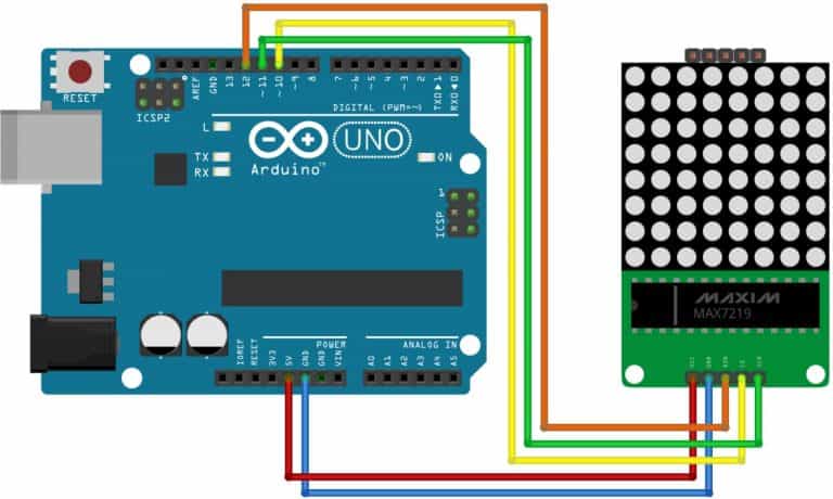
1 2 3 4 5 | D10 ------------------LOAD or CHIP SELECT of LED module D11 ------------------CLOCK of LED module D12 ------------------DATA IN of LED module +5V ------------------VCC of LED module GND ------------------GND of LED module |
Part 1 : Indentify the pins of 8*8 LED Dot Matrix Module
https://www.youtube.com/watch?v=ZXF62U0ziJ8
Part2: How to display Scrolling Text on 8*8 LED Dot Matrix
https://www.youtube.com/watch?v=cO_O4s2Swus
HOW TO MAKE SCROLLING TEXT LED DISPLAY || 48X8 LED MATRIX || Huge LED Matrix BY MANMOHAN PAL
https://www.youtube.com/watch?v=-nSiwW6jl6U
How to make custom characters for Arduino LCD by Manmohan Pal
https://www.youtube.com/watch?v=tWddnbe69ng
Arduino Text Scrolling Display |xcluma MAX7219 4 In 1 Display with 5P Line Dot Matrix Module
https://www.youtube.com/watch?v=KsSXvtmCINQ
Code Generator: https://docs.google.com/spreadsheets/d/1tuGgGR3pGKJ3ioA_QQ92Hibe33dUl5cM/edit?usp=sharing&ouid=105843565998608894777&rtpof=true&sd=true
Download Library : https://drive.google.com/file/d/1Oul8NxS-W86z_p51lbIAgG1IqKnWR_ZU/view?usp=sharing
How to install Libraries in Arduino IDE by Manmohan Pal
https://www.youtube.com/watch?v=LWlq25J2hFI
/////////////////////////////////////////Code///////////////////////////////
#include <LedControl.h>
int DIN = 12;
int CS = 11;
int CLK = 10;
byte A[8]={B00111100,B01111110,B01100110,B01100110,B01111110,B01111110,B01100110,B01100110,};
byte B[8]={B01111100,B01100110,B01100110,B01111100,B01111100,B01100110,B01100110,B01111100,};
byte C[8]={B00111100,B01111110,B01100010,B01100000,B01100000,B01100010,B01111110,B00111100,};
byte house[8]={B00011000,B00111100,B01100110,B11000011,B01000010,B01011010,B01011010,B01011010,};
LedControl lc=LedControl(DIN,CLK,CS,0);
void setup(){
lc.shutdown(0,false); //The MAX72XX is in power-saving mode on startup
lc.setIntensity(0,15); // Set the brightness to maximum value
lc.clearDisplay(0); // and clear the display
}
void loop(){
printByte(A);
delay(1000);
printByte(B);
delay(1000);
printByte(C);
delay(1000);
printByte(house);
delay(1000);
}
void printByte(byte character [])
{
int i = 0;
for(i=0;i<8;i++)
{
lc.setRow(0,i,character[i]);
}
}
//////////////////////////////////////end///////////////////////////////////////////////
Manmohan Pal
Mob. 8989811397
Email- mannmohanpal@gmail.com
Blog: http://electronics4ubymanmohanpal.blogspot.in/p/blog-page_5.html
Youtube Channel: https://www.youtube.com/channel/UCDnhARnHOEIPuNIEp5vPdGQ
RF Remote Control Car Using 433 Mhz RF transmitter and Receiver Kit by Manmohan Pal
https://www.youtube.com/watch?v=rcaQluS7Gzw
RF Remote Control Circuit Using 433 Mhz Module and HT12E Encoder and HT12D Decoder IC by Manmohan
https://www.youtube.com/watch?v=51TNQiaXm3U
IC L293 Moter Driver H Bridge IC by Manmohan Pal
https://www.youtube.com/watch?v=1Gh-aVm5rDg
RF Remote Control Circuit Using 433 Mhz Module and HT12E Encoder and HT12D Decoder IC by Manmohan
https://www.youtube.com/watch?v=51TNQiaXm3U
Wireless 4 Channel 433 Mhz RF Remote Control Transmitter and Receiver Unboxing by Manmohan Pal
https://www.youtube.com/watch?v=ZFjDGuFBMnI
433 Mhz RF Module Tx and Rx with Arduino Nano, RF Remote Control Circuit by Manmohan Pal
https://www.youtube.com/watch?v=JHN7kgguCG8
Wireless 4 Channel 433 Mhz RF Remote Control Transmitter and Receiver Unboxing by Manmohan Pal
https://www.youtube.com/watch?v=ZFjDGuFBMnI
RF 4 Channel Remote Control Relay Module using 433 Mhz RF Transmitter and Reciever bu Manmohan Pal
https://www.youtube.com/watch?v=1bgBXruwxfE&t=58s
https://www.youtube.com/watch?v=C1qGVaGgGOo
Touch Switch using NAND gate IC 4011 by Manmohan Pal
https://www.youtube.com/watch?v=jIEKWVs8d40
Touch Switch || Toggle aswitch || Touch ON Touch Off Switch using IC 4017
https://www.youtube.com/watch?v=9iA0AtnrL7A
433 Mhz RF Module Tx and Rx with Arduino Nano, RF Remote Control Circuit by Manmohan Pal
https://www.youtube.com/watch?v=JHN7kgguCG8&t=607s
Remote Control Relay Module 4 Channel 5 volt by Manmohan Pal
https://www.youtube.com/watch?v=67_CzDsuyfw
Remote control for every home appliance
https://www.youtube.com/watch?v=mUuSYWyD7Ic
Remote operated light- by Manmohan Pal
https://www.youtube.com/watch?v=5oP1SCkVJm8
Remote control Fan- IR remote control Circuit using IC 555 Timer by Manmohan Pal
https://www.youtube.com/watch?v=GvAZadfdIAE
Arduino Nano Unboxing| Uploading First Program on Arduino Nano- By Manmohan Pal
https://www.youtube.com/watch?v=OxQcPwc8Wl0


No comments:
Post a Comment